

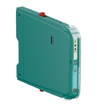
Switch Amplifier HiC2842
- 2-channel isolated barrier
- 24 V DC supply (bus powered)
- Dry contact or NAMUR inputs
- 2 passive transistor outputs
- Line fault detection (LFD)
- Reversible mode of operation
- Up to SIL 2 (SC 3) acc. to IEC/EN 61508


Please note: All product-related documents, such as certificates, declarations of conformity, etc., which were issued prior to the conversion under the name Pepperl+Fuchs GmbH or Pepperl+Fuchs AG, also apply to Pepperl+Fuchs SE.
Datasheet excerpt: Technical data of HiC2842
| General specifications | ||
|---|---|---|
| Signal type | Digital Input | |
| Functional safety related parameters | ||
| Safety Integrity Level (SIL) | SIL 2 | |
| Systematic capability (SC) | SC 3 | |
| Supply | ||
| Connection | SL1: 1a, 1b(-); 2a, 2b(+) | |
| Rated voltage | 19 ... 30 V DC bus powered via Termination Board | |
| Ripple | ≤ 10 % | |
| Rated current | ≤ 30 mA | |
| Power dissipation | ≤ 600 mW | |
| Power consumption | ≤ 700 mW | |
| Input | ||
| Connection side | field side | |
| Connection | SL2: 5a(+), 5b(-); 1a(+), 1b(-) | |
| Rated values | acc. to EN 60947-5-6 (NAMUR), see manual for electrical data | |
| Open circuit voltage/short-circuit current | approx. 10 V DC / approx. 8 mA | |
| Switching point/switching hysteresis | 1.2 ... 2.1 mA / approx. 0.2 mA | |
| Line fault detection | breakage I ≤ 0.1 mA , short-circuit I ≥ 6.5 mA | |
| Pulse/Pause ratio | min. 100 µs / min. 100 µs | |
| Output | ||
| Connection side | control side | |
| Connection | SL1: 8a(+), 7a(-); 10a(+), 9a(-) | |
| Rated voltage | 30 V DC | |
| Rated current | 50 mA | |
| Response time | ≤ 200 µs | |
| Signal level | 1-signal: (external voltage) - 1 V max. for 50 mA (Tamb = 25 °C (77 °F)) 0-signal: blocked output (off-state current ≤ 10 µA) |
|
| Output I | signal ; Transistor | |
| Output II | signal ; Transistor | |
| Fault indication output | ||
| Connection | SL1: 6b | |
| Output type | open collector transistor (internal fault bus) | |
| Transfer characteristics | ||
| Switching frequency | ≤ 5 kHz | |
| Galvanic isolation | ||
| Output/power supply | basic insulation acc. to EN 50178, rated insulation voltage of 50 V AC | |
| Output/Output | basic insulation acc. to EN 50178, rated insulation voltage of 50 V AC | |
| Indicators/settings | ||
| Display elements | LEDs | |
| Control elements | DIP switch | |
| Factory setting | input close, transistor closed, lead fault detection enabled | |
| Configuration | via DIP switches | |
| Labeling | space for labeling at the front | |
| Directive conformity | ||
| Electromagnetic compatibility | ||
| Directive 2014/30/EU | EN 61326-1:2013 (industrial locations) | |
| Conformity | ||
| Galvanic isolation | EN 50178:1997 | |
| Electromagnetic compatibility | NE 21:2017 For further information see system description. |
|
| Degree of protection | IEC 60529:2001 | |
| Protection against electrical shock | IEC 61140 | |
| Ambient conditions | ||
| Ambient temperature | -40 ... 70 °C (-40 ... 158 °F) | |
| Relative humidity | ≤ 90 % , non-condensing | |
| Mechanical specifications | ||
| Degree of protection | IP20 | |
| Mass | approx. 100 g | |
| Dimensions | 12.5 x 106 x 128 mm (0.5 x 4.2 x 5.1 inch) (W x H x D) | |
| Height | 106 mm | |
| Width | 12.5 mm | |
| Depth | 128 mm | |
| Mounting | on termination board | |
| Coding | pin 1 and 2 trimmed For further information see system description. |
|
| Data for application in connection with hazardous areas | ||
| EU-type examination certificate | BVS 09 ATEX E 157 | |
| Marking |  II (1)G [Ex ia Ga] IIC II (1)D [Ex ia Da] IIIC I (M1) [Ex ia Ma] I II (1)G [Ex ia Ga] IIC II (1)D [Ex ia Da] IIIC I (M1) [Ex ia Ma] I |
|
| Input | Ex ia, Ex iaD | |
| Voltage | 10.5 V | |
| Current | 17.1 mA | |
| Power | 45 mW (linear characteristic) | |
| Supply | ||
| Maximum safe voltage | 253 V AC (Attention! Um is no rated voltage.) | |
| Output | ||
| Maximum safe voltage | 253 V AC (Attention! The rated voltage can be lower.) | |
| Galvanic isolation | ||
| Input/Output | safe electrical isolation acc. to IEC/EN 60079-11, voltage peak value 375 V | |
| Input/power supply | safe electrical isolation acc. to IEC/EN 60079-11, voltage peak value 375 V | |
| Directive conformity | ||
| Directive 2014/34/EU | EN IEC 60079-0:2018+AC:2020 , EN 60079-11:2012 , EN 50303:2000 | |
| International approvals | ||
| UL approval | E106378 | |
| Control drawing | 116-0331 | |
| IECEx approval | ||
| IECEx certificate | IECEx BVS 09.0060 | |
| IECEx marking | [Ex ia Ga] IIC , [Ex ia Da] IIIC , [Ex ia Ma] I | |
| General information | ||
| Supplementary information | Observe the certificates, declarations of conformity, instruction manuals, and manuals where applicable. For information see www.pepperl-fuchs.com. | |
Classifications
| System | Classcode |
|---|---|
| ECLASS 13.0 | 27210121 |
| ECLASS 12.0 | 27210121 |
| ECLASS 11.0 | 27210121 |
| ECLASS 10.0.1 | 27210121 |
| ECLASS 9.0 | 27210121 |
| ECLASS 8.0 | 27210121 |
| ECLASS 5.1 | 27210121 |
| ETIM 9.0 | EC001485 |
| ETIM 8.0 | EC001485 |
| ETIM 7.0 | EC001485 |
| ETIM 6.0 | EC001485 |
| ETIM 5.0 | EC001485 |
| UNSPSC 12.1 | 32101514 |
Details: HiC2842
This isolated barrier is used for intrinsic safety applications.
The device transfers digital signals ( NAMUR sensors/mechanical contacts) from the explosion-hazardous area to the non-explosion-hazardous area.
Each input controls a passive transistor for the non-explosion-hazardous area load.
Via switches the mode of operation can be reversed and the line fault detection can be switched off.
During a fault state, the transistors revert to their de-energized state and LEDs indicate the fault according to NAMUR NE 44. A separate fault bus is available. This fault bus can be monitored if the termination board supports a module fault detection.
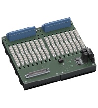
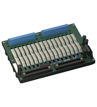
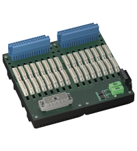
This device mounts on a HiC termination board.
Datasheet: HiC2842
| Datasheet | File Type | File Size |
|---|---|---|
| Datasheet HiC2842 | 943 KB | |
| Fiche de données HiC2842 | 879 KB | |
| Datenblatt HiC2842 | 949 KB | |
| Datasheet HiC2842 | 887 KB | |
| Hoja de datos HiC2842 | 878 KB |
Documents: HiC2842
| Manuals | File Type | File Size |
|---|---|---|
| System Manual | 5438 KB | |
| Systemhandbuch | 5450 KB | |
| Instruction manuals | ||
| Инструкции | 161 KB | |
| Instruction manual / Betriebsanleitung | 308 KB | |
| Návod k poużití | 157 KB | |
| Instruktions manual | 157 KB | |
| Instruction manual | 160 KB | |
| Kasutusjuhend | 153 KB | |
| Käyttöohje | 153 KB | |
| Manuel d'instructions | 157 KB | |
| Betriebsanleitung | 162 KB | |
| Οδηγίες χρήσης | 164 KB | |
| Handleiding | 156 KB | |
| Instruction manual / Betriebsanleitung | 156 KB | |
| Használati útmutató | 158 KB | |
| Manuale di istruzioni | 156 KB | |
| Lietošanas pamācība | 156 KB | |
| Instrukciju vadovas | 157 KB | |
| Instrukcja obsługi | 159 KB | |
| Manual de instruções | 156 KB | |
| Manual de utilizare | 156 KB | |
| Návod na poużitie | 157 KB | |
| Navodila za uporabo | 155 KB | |
| Manual de instrucciones | 157 KB | |
| Manual | 154 KB | |
| Documents | ||
| Functional Safety Manual | 1972 KB | |
| Handbuch funktionale Sicherheit | 1940 KB |
CAD+CAE: HiC2842
| CAD | File Type | File Size |
|---|---|---|
| CAD 3-D / CAD 3-D | STP | 2770 KB |
| CAD Portal / CAD Portal | LINK | --- |
| EPLAN | ||
| EPLAN macros H-System devices (EMA) / EPLAN-Makros Geräte H-System (EMA) | ZIP | 3536 KB |
Approvals+Certificates: HiC2842
| Certificates | File Type | File Size |
|---|---|---|
| China SITIIAS CCC Ex Certificate | 1044 KB | |
| Europe DEKRA EXAM II (1) D I (M1) II (1) G | 1314 KB | |
| USA Canada UL Hazardous Location Certificate of Compliance cULus UL E106378 | 565 KB | |
| United Kingdom CML UK-Type Examination Certificate UKEX Category (1) D UKEX Category (1) G UKEX Category (M1) | 152 KB | |
| Worldwide DEKRA EXAM IECEx Certificate of Conformity | LINK | --- |
| exida Functional Safety Assessment | 370 KB | |
| Control Drawings | ||
| Control drawing UL / Control drawing UL | 136 KB | |
| Declaration of Conformity | ||
| EU Declaration of Conformity (P+F) / EU-Konformitäterklärung (P+F) | 81 KB | |
| UK Declaration of Conformity (P+F) / UK-Konformitäterklärung (P+F) | 76 KB |
Associated Products: HiC2842
| Accessory of | ||||||
|---|---|---|---|---|---|---|
|
||||||
|
||||||
|
||||||


Several hundred products with a SIL/PL assessment, free tools, and brochures in one place: the "Functional Safety Hub" is your starting point when you have to implement safety functions.


Pepperl+Fuchs SE
Lilienthalstraße 200
68307 Mannheim
Germany
info@de.pepperl-fuchs.com
 +49 621 776-0
Pepperl+Fuchs is a leading developer and manufacturer of electronic sensors and components for the global automation market. Continuous innovation, enduring quality, and steady growth have been the foundation of our success for more than 70 years. Pepperl+Fuchs employs 6,300 people worldwide and has manufacturing facilities in Germany, USA, Singapore, Hungary, Indonesia and Vietnam, most of them ISO 9001 certified.